
The wire


Jorge in action
The four treatments

The four irrigation treatments in the field plot are:
- control: irrigates on a set schedule whatever the circumstances.
- rain sensor: a simple rain sensor either allows or prevent the automated schedule.
- soil water sensor: a soil water sensor either allows or prevents automated irrigation based on a set soil water content threshold.
- weather-based: the timer uses temperature, rain depth, and landscaping specifics to calculate the duration of irrigation events within set parameters.

Grudge match: rain sensor v. on-site weather station
These four treatments are divided among three timers. How? Well, since an activated rain sensor effectively paralyzes all timer function, this treatment is assigned its own clock. Likewise for the weather-based treatment, as this timer is its own entity. This leaves one timer to pull double-duty as both the control and the soil water sensor treatments – 8 valves on two zones. What!? Enter the relay box!

A relay box allows a low-voltage digital irrigation timer to fire multiple solenoid valves at once without dissipation of the 24V electrical charge. In the interest of science, the relay box allows a specific treatment's reps to turn on at the same time; therefore each is subject to all the variables present at that specific moment. In the case of the control/soil water sensor treatment, each treatment wire moves into the relay box, then out from the box to the valve platforms, where it is broken 4 times, one for each rep valve.
Going underground!

A lysimeter can be loosely defined as a container used to capture water as it percolates, via gravity, down the soil column. In addition to volume, the captured water can also be analyzed for soluble constituents.

The lysimeter design of choice for the field plot is based on the size of the hole possible with available drilling equipment. Although irrigation events will be programmed to apply 0.5” of water, the lysimeter is designed to collect up to a 1.5” rainfall event, which is common in South Florida.

Once the lysimeter prototype proved effective in the field following an early August deluge, mass production was initiated.

Each lysimeter consists of the following materials:
· 23” of 1.5” PVC pipe
· 1.5” cap
· 2:1.5” reducer
· PVC drain with 2” opening (lysimeter top)
· ½” female-threaded coupling
· 3 elbows (1/2” male-threaded with 3/8” barb)
· 3/8” plastic tubing (clear and mesh-reinforced)
· ½” PVC
· Fiberglass screen
· Acid-washed sand
· PVC glue and primer
· Hot glue
· Weather-resistant sealant

The Baseline conundrum

Wiring the other irrigation treatments is logical enough, but how in the world are 4 soil water sensors wired to one timer and so that each of them produces a unique soil water content reading for its specific rep?


Turf in a rep is prepared for sensor insertion

Four soil water sensors, four unique soil water content readings
Drill, baby, drill!

Nick & Tina on drill detail
Lysimeter installation was completed using the following methodology:
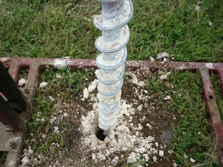
A top layer of soil and grass was removed with a shovel (approximately 1 foot in diameter was removed) and a hole was drilled in 12 of the 16 plots, approximately 30” deep.


Then a tunneling bar was used to chip away the bedrock and soil was removed so that the top of the lysimeter could lay just below the rooting zone.

The lysimeter was placed in the hole and the top was filled about halfway with the acid-washed sand.


The next step

With several matters still left to resolve (such as fertilization and lysimeter sampling frequency, treatment uniformity tests, soil water sensor calibrations, etc.), the field plot remains a few weeks away from its formal inauguration. Stay tuned for further developments!
Great pics! I hope I get copies! Also, great job to Nicki for pulling this project together!
ReplyDelete